
Introduction
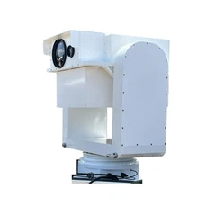
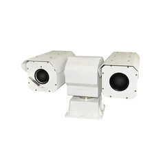
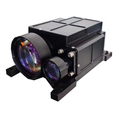
This manual provides detailed guidance on aligning the optical axis of the LRF6520 laser rangefinder (As well it may be applicable for other LRF models by principle) with a customer's camera system. The LRF6520, a high-performance 20 km rangefinder with a 1.54 μm wavelength, ≤0.3 mrad beam divergence, and robust environmental adaptability (-55°C to +70°C operating range), benefits from precise alignment to integrate ranging data seamlessly with imaging. This ensures accurate target acquisition in applications like UAV surveillance, military targeting, and industrial inspection. The procedures below preserve the core principles from the original guidelines while incorporating industry best practices, such as coaxial pointer technology for merged beams and schematic calibration diagrams, to enhance accuracy and reliability.
Core Principles of Optical Axis Alignment
To achieve precise optical axis alignment, two core conditions must be met, both of which are indispensable.
- Optical Center Coaxiality: The laser emission/reception center of the laser rangefinder and the optical center of the camera lens must be physically aligned along the same straight line in space. For the LRF6520, this can be facilitated using coaxial pointer technology, where a secondary laser (e.g., visible pointer) merges with the ranging beam through shared optics, ensuring emission from the same aperture and minimizing parallax.
- Field of View Center Consistency: The ranging field of view center of the LRF6520 (the area covered by the laser spot) and the imaging field of view center of the camera (displayed on the screen or in photographs) must point to the same target point. This alignment accounts for the device's spatial pointing instability (≤0.03 mrad) and is critical under atmospheric turbulence.
Commonly Used Optical Axis Alignment Methods
(Listed by Accuracy from Low to High)
Depending on the precision requirements of the application scenario, different optical axis alignment methods can be selected. Below are the three most commonly used schemes, tailored for the LRF6520 with enhancements like beam path verification and software-assisted pixel analysis.
1. Simple Visual Method (Low Accuracy, Suitable for Temporary Calibration)
No professional equipment is needed, suitable for scenarios with low precision demands (e.g., daily outdoor shooting and ranging).
Secure the LRF6520 and camera on the same bracket, ensuring tight adhesion and no relative movement.
Aim at a high-contrast target over 100 meters away (e.g., distant road signs or building edges).
- First, align the LRF6520 to the target and complete ranging, noting the target's position within the rangefinder's field of view.
- Observe the camera screen and adjust the camera angle to center the same target on the camera's crosshair (or grid lines).
- Repeatedly fine-tune the bracket or device angles until the targets aligned by the rangefinder and camera completely coincide. Verify using the LRF6520's 1 Hz repetition frequency for real-time feedback.
2. Target Board Calibration Method (Medium Accuracy, Suitable for Most Industrial Scenarios)
Uses a dedicated target board for quantitative calibration, precision higher than visual method, one of the most commonly used calibration methods.
- Set up a calibration target board with crosshairs in an open area, the center needs a clear marker (e.g., black dot), distance recommended 200-500 meters (longer distance, smaller calibration error).
- Fix the LRF6520 and camera through a rigid bracket, ensuring no displacement between devices, bracket needs to be placed level and stable.
- First adjust the LRF6520, making its laser spot precisely fall on the target board center marker, record the rangefinder angle parameters (e.g., azimuth angle, elevation angle).
- Then adjust the camera, through the camera's viewfinder or screen, make the target board center marker completely coincide with the camera's field of view center (can enable camera's "grid line" or "level" assistance).
- Repeat the above steps respectively at the target board's upper, lower, left, right four offset positions, verify if the optical axis is consistent at different angles, if there is deviation then fine-tune again. Incorporate beam path checks to confirm no deviation due to the LRF6520's beam divergence.
3. Professional Equipment Calibration Method (Highest Accuracy, Suitable for High-Precision Scenarios)
Uses optical instruments for precise calibration, suitable for scenarios with extremely high precision requirements.
- Core Equipment: Parallel light tube, optical platform, high-precision two-dimensional adjustment rack.
- Mount the LRF6520 and camera on the high-precision two-dimensional adjustment rack, fixed on the optical platform, ensuring device stability without vibration.
- Let the parallel light tube simulate infinite distance target, the parallel light tube's cross reticle center is the calibration benchmark point.
- Adjust the LRF6520, making its received parallel light tube signal center align with the laser emission center, record adjustment rack parameters.
- Adjust the camera, through image acquisition software analyze the camera captured parallel light tube reticle image, making the reticle center coincide with the camera's imaging center (through pixel coordinate calculation).
- Use calibration software to record and save adjustment parameters, form calibration file, some devices can directly load parameters to achieve automatic axis alignment. Enhance with coaxial integration if possible, merging beams for zero-parallax at all distances.
Key Precautions
- Fixation Stability: Must fix both on a rigid bracket before aligning the axis, avoid device shaking during calibration, otherwise it will cause calibration result failure. For the LRF6520, leverage its shock resistance (15 g peak) for stable mounting.
- Calibration Distance: Try to choose far distance target (recommend ≥100 meters), near distance calibration will amplify angle deviation, leading to sharp increase in error when using at far distance.
- Environmental Impact: Avoid calibration in strong light, strong wind, haze weather, strong light will interfere with laser reception, strong wind will cause device displacement, haze will weaken laser signal and camera imaging clarity. Align with LRF6520's visibility requirements (≥23 km for max range).
- Regular Re-inspection: After calibration, recommend re-inspection every 3-6 months, especially after device experiences vibration, collision or long-term use, the optical axis may shift. Use the LRF6520's self-test features for ongoing validation.
Liability Exemption Terms
This manual is provided for reference purposes only. The alignment procedures are general guidelines based on the LRF6520's specifications and do not account for the specific design, configuration, or condition of the customer's camera system, which is beyond our knowledge or control. We have no obligation to ensure compatibility with customer-provided equipment. Any misoperation, damage, malfunction, or injury resulting from the use of this manual-including improper alignment, equipment failure, or environmental factors-is the sole responsibility of the user. Customers are advised to consult their camera manufacturer's documentation, conduct thorough testing, and seek professional assistance if needed. The manufacturer disclaims all liability for any consequences arising from the application of these instructions.
Click Here for more information about our LRF6520 20km LRF.